Safety Integrated OverviewControl/drive systemIn order to implement safety-related measures, up until now, external equipment and devices were used - e.g. contactors, switches, cams and monitoring devices. If a hazardous situation is detected, these devices generally interrupt the power circuit thus stopping the motion, see image below. With the integration of safety functions, drive systems and CNC controls perform safety functions in addition to their functional tasks. Very short response times can be achieved because of the short data paths from acquisition of the safety-related information - e.g. speed or position - up to evaluation. The systems with integrated safety technology generally respond very quickly when the permissible limit values are violated, e.g. position and velocity limit values. They can be of decisive importance for the required monitoring result. The integrated safety technology can directly access the power semiconductors in the drive controller without using electromechanical switching devices in the power circuit. This helps reduce the susceptibility to faults - and the integration also reduces the amount of cabling. 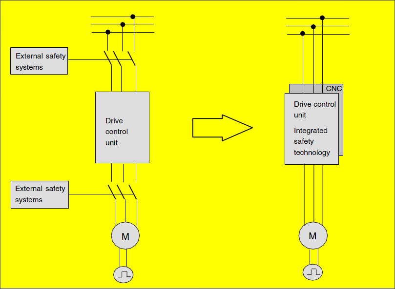
SINUMERIK Safety IntegratedUsing the "SINUMERIK Safety Integrated" function, for SINUMERIK 840D sl, for all power/performance classes, integrated safety functions are available in conjunction with the SINAMICS S120 drive system; these are used to monitor standstill (zero speed), velocity and position. SINAMICS S120 is used in conjunction with 1FT6/1FK6/1FK7 three-phase servomotors and 1FN linear motors for feed drives as well as 1FE and 1PH motors for main spindle drives. The safety-related sensors and actuators are connected through distributed I/O via PROFIBUS-DP with the PROFIsafe profile, e.g. ET 200S, ET 200eco. This means that a complete digital system is available that is suitable for complex machining tasks. SI System Structure and Basic FeaturesA two-channel, diverse system structure is formed on the basis of an existing multiprocessor structure. 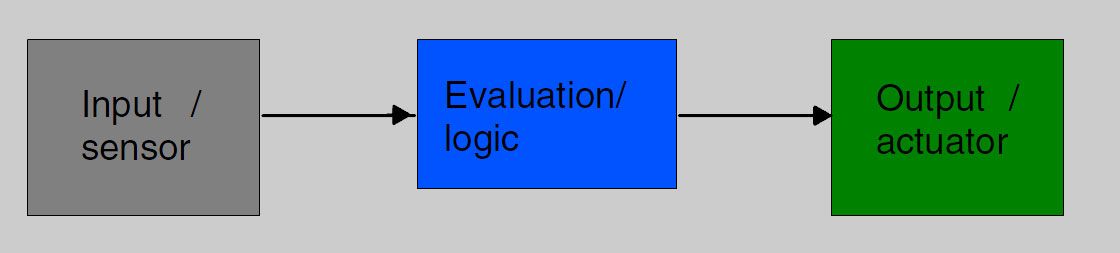
Features of the Two-Channel, Diverse StructureA two-channel, diverse structure is characterized by the following features:
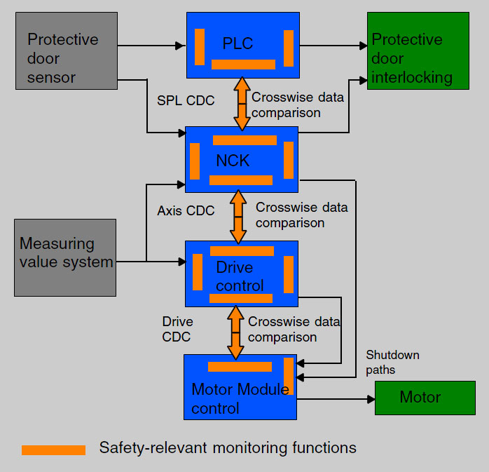
SensingThe actual values of the individual axes are sensed by the sensor modules through two channels and are provided to the drive and control. In order to connect sensors and actuators in a safety-related fashion, their process signals must be connected-in for further processing. EvaluatingThe safety-related functions are executed independently of one another by the NCK-CPU, PLC-CPU and the drive CPUs. The CPUs cyclically and mutually compare their safety-related data and results (crosswise data comparison). A test can be carried-out - initiated by the CPUs - to check the shutdown paths and actuators (forced checking procedure). RespondingWhen the integrated safety-relevant functions respond, the drive processors, the PLC processor and/or the NCK processor can act on the connected actuators in a safety-relevant fashion in-line with the actual situation. For example, the appropriate stop responses for the drives can be initiated and the actuators shutdown via the shutdown paths. Overview, SI functionsThe safety-related functions are available in all of the operating modes and can communicate with the process via safety-related input/output signals. These can be implemented individually for each axis.
|